 EN
EN DE
DE ES
ES FR
FR PT
PT IT
IT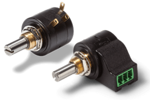

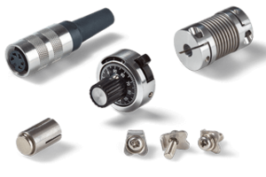


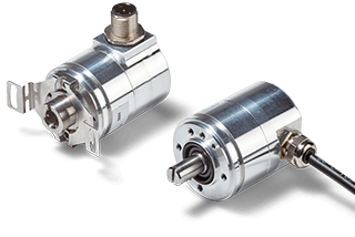
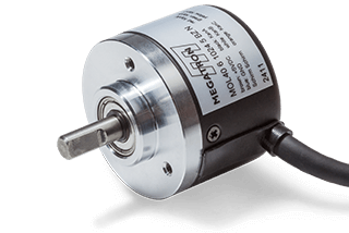
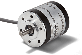
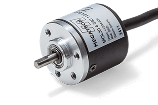
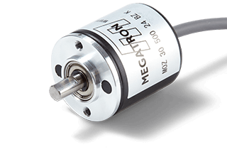
Rotary Encoders
With analog, digital or incremental interfaces in single or multiturn versions
Guide Rotary Encoders
Index
What is a rotary encoder?

Encoders detect or specify angular positions/positions and convert this information into electrical signals. They are angle sensors that transmit their measured value without contact to an electronic system. This is what distinguishes them from potentiometers, which are passive components. Basically, each encoder consists of a housing, electronics with the sensor as the heart of the measurement and the electrical connection. Depending on the version, the sensor may also include a shaft with a bearing to mechanically produce the angle measurement. There are many related terms for the word encoder. However, if the angle is provided as a complete value (i.e. as an absolute value) with a fixed reference to a zero position, then the rotary encoder is referred to as an absolute encoder. If only the change in angle is provided, i.e. the output signal provides only relative information, then the encoder is an incremental encoder. This guide only describes non-contact technologies using magnetic or optical measurement principles.
What does "contactless" or "non-contact" mean?
Non-contact means that the measurement is transmitted to the electronics without contact. For example, a rotating part of the application is connected to the shaft of the encoder and the measurement is received by the electronics. However, there is no direct mechanical connection between the two components. The measured value is therefore transmitted without contact (contactless).
All contactless encoders from MEGATRON are based either on magnetism or on an optical measuring principle. With magnetic encoders there is practically no wear on the acquisition (electronics) and with optical encoders only the optical detection unit has a limited lifespan. The only significant wear in contactless encoders occurs in the mechanical components used to record the measured values when there is a shaft and shaft bearing.
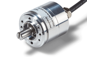
Magnetic rotary encoder with Hall effect
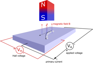
The Hall effect, named after Edwin Hall, describes the occurrence of an electrical voltage, known as the Hall voltage, in a current-carrying conductor (Hall element) located in a stationary magnetic field. If a circular, diametrically magnetized (north pole/south pole) permanent magnet is placed over a Hall element, the magnet is rotated and the voltage at the output of the amplifier circuit is measured, a sinusoidal output voltage curve is measured.
In principle, external magnetic fields can interfere with this technology. So-called gradient-based Hall sensors, which are largely insensitive to these disturbances, are mainly used. See our guide on absolute encoders for more details.
| Advantages of magnetic encoders | Disadvantages of magnetic encoders |
|
|
Optical encoders
Optical encoders are based on a non-contact optical scanning principle. Light is generated by a light-emitting diode, which shines through a code wheel onto a photodetector. The photodetector generates an electrical signal which is processed by the electronics and used to output the measured value.
In non-contact rotary encoders with optical scanning systems, the light-emitting diodes are subject to a continuous ageing process during operation. In addition, dust on the optical system contributes to the ageing of the sensor.
See our guide to incremental encoders for more details.
Coding wheel
Click here for an overview of all optical incremental encoders.
| Advantages of optical encoders | Disadvantages of optical encoders |
|
|
Incremental encoders
Incremental encoders output a number of rectangular signals instead of information proportional to the angle (see absolute encoders). They are also known as pulses. Incremental encoders are therefore also called pulse encoders and the number of pulses per revolution is always given (unit imp./rev.). One pulse corresponds to one period duration. The term "one increment" is also used to refer to a period of time. This also explains the term incremental encoder. An external evaluation unit, such as a counter, is always required to evaluate the measurement result of an incremental encoder.

Signal sequence incremental encoder
Pay particular attention to the following points:
- For an angle measurement, the number of pulses must be counted in an external evaluation unit and the sum of the pulses must be converted into an angle.
- If the power supply to the counter is interrupted, the counter information is usually lost. If the absolute value of the angle relative to a reference point is to be measured or calculated, referencing must be carried out by passing through the zero position.
- For a speed measurement, the number of pulses per time is calculated.
Incremental encoders are available with different numbers of pulses per revolution. For example, 360 pulses/revolution means that 360 pulses (360 signal periods) are output per full shaft revolution (360°). If, for example, 1024 pulses/revolution are specified, this means that 1024 pulses (1024 signal periods) are output per full shaft revolution (360°). Incremental encoders are available from MEGATRON as Hall encoders and as optical encoders. A detailed description can be found in the incremental encoder guide.
Absolute encoders
Absolute encoders output an analogue or digital signal proportional to the angle. There is therefore a fixed reference point for the angle measurement. Encoders with an analogue output provide the measured angle as an output voltage, output current or pulse width (PWM). Digital interfaces for the output of absolute values are available in the form of communication protocols. See the absolute encoder guide for a detailed description.
Analogue output signal from a singleturn absolute encoder
| Measured angle [°, degrees] | Output voltage [Volt] |
| 0° | 0 V |
| 360° | 10 V |
| 45° | 1.25 V |
| 90° | 2.5 V |
| 180° | 5 V |
| 360° | 10V |
The table shows the output voltage curve at different measurement angles using a 0...10 V voltage output as an example.
Single- vs. Multiturn encoders
Singleturn encoders
Singleturn encoders are absolute encoders that can only measure the angle of one full revolution. After a full revolution, the output signal will be the same as at 0° every 360°. Most singleturn absolute encoders measure the full angle range from 0° to a maximum of 360°. Only a few products measure angles in a limited angular range, for example ±45°.
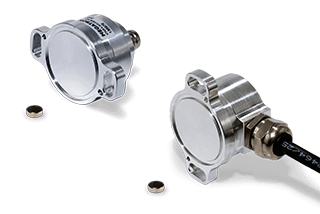
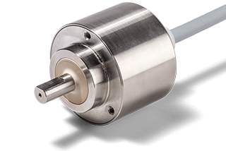
Multiturn encoders
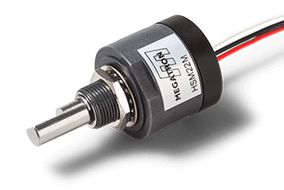
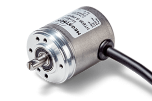
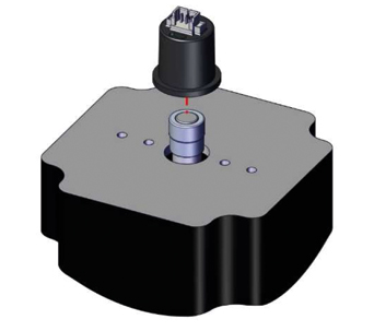
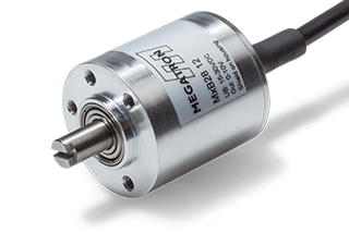
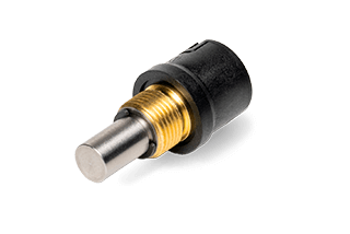
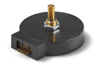
True-Power-On absolute encoder HSM22M
Compared to single-turn encoders, multiturn encoders are capable of measuring angles beyond 360°. The measuring system is capable of counting the number of revolutions and is usually programmed so that the signal rises continuously over the maximum electrically effective angular range. For example, certain MEGATRON multiturn absolute encoders can measure angles up to a maximum of 72000° (up to 200 shaft revolutions). Click here for an overview of all multiturn encoders.
Without special precautions, such encoders will lose their position information if the power supply is interrupted. One class of multiturn encoders are true power-on encoders. Such an encoder provides a correct output signal even if the angle of rotation changes as desired during a temporary loss of power.
Actual value device and setpoint device
The two terms "actual value device" and "setpoint device" are defined by their purpose in the application. Some encoder models can be used for both purposes.
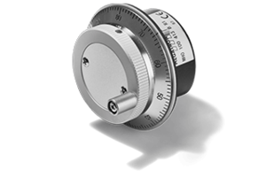
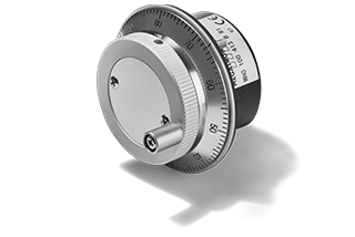
In a setpoint device, a value is set manually. A setpoint is set by manually turning the encoder shaft (usually via a knob mounted on the shaft). These knobs are used in control panels, for example, to navigate through menus or to set various parameters for measuring instruments. Click here for an overview of manual input devices.
Actual value encoder is used as a synonym for angle sensor or rotary encoder when an angle is simply measured and not manually specified. As this does not necessarily correspond to the setpoint in an application, the two terms are used to differentiate. Setpoint and actual value transmitters can be part of control loops.

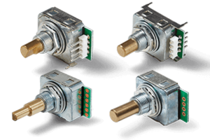
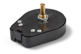
MRX50 rotary encoder as setpoint devices
Angular properties and direction of rotation
Mechanical angle of rotation
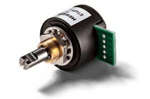
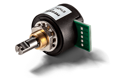
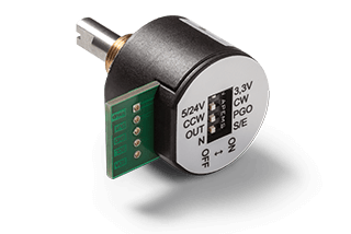
The mechanical angle of rotation is the total angle at which the encoder can be mechanically operated. For most contactless encoders, the mechanical angle of rotation is not mechanically limited, i.e. the shaft of the encoder can be rotated continuously clockwise and counterclockwise without stopping the rotation. With a few exceptions, mechanical end stops are available. These are particularly useful for setpoint devices (manual adjusters). An example is the ETAM25 series from MEGATRON, which has mechanical end stops.

Electrical and mechanical rotation angle and direction information for the ETAM25 series
Electrically effective angle of rotation
The electrically effective angle of rotation is the angular range in which the output signal changes. The following diagrams show example output functions of singleturn absolute encoders. In both cases, the mechanical angle of rotation is 360°.
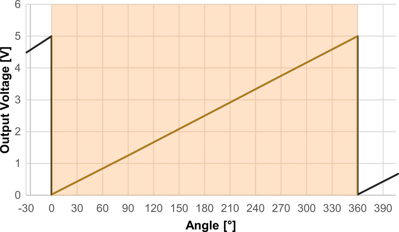
Example 1
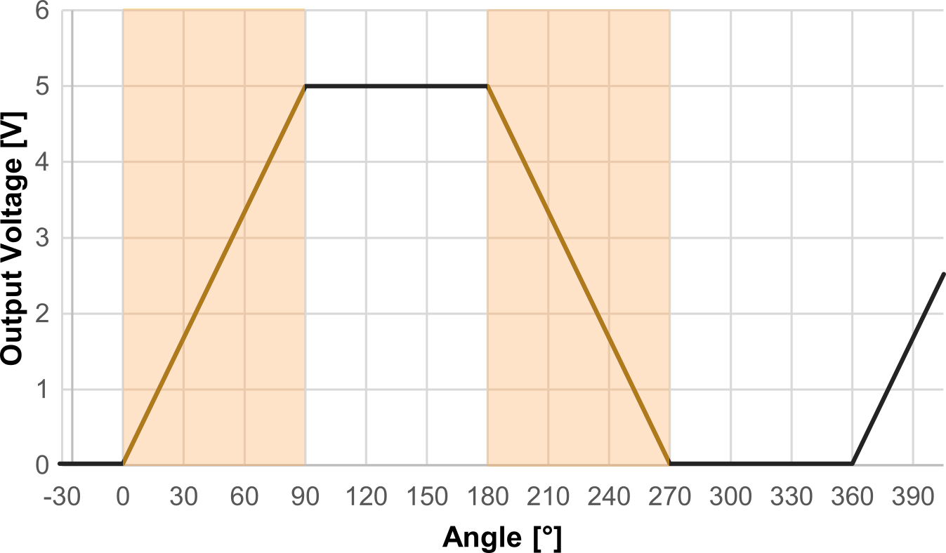
Example 2
- In the first example, the encoder signal changes over the entire angular range of 0...360°. The range shown in orange is the electrically effective angle of rotation.
- In the second example, by programming the output signal differently, there are two different areas where a signal change occurs: Here the electrically effective angle of rotation is in the range between 0°...90° and between 180°...270°.
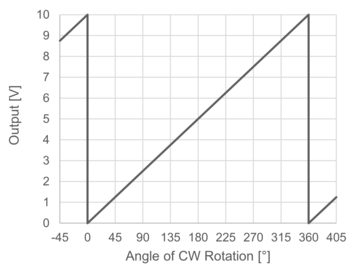
Sense of rotation (CW/CCW)
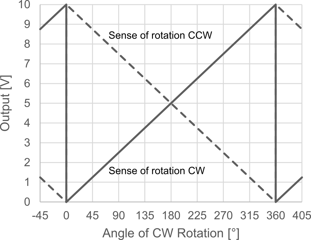
When programming the output waveform, it is important to specify the sense of rotation of the desired output waveform. The sense of rotation must be specified when describing the desired output waveform so that there is an unambiguous relationship between the signal and the direction of rotation of the shaft.
The direction of rotation of the shaft is given when the encoder is viewed from the front. That is, when the observer is looking at the shaft bearing and the shaft end. For a kit encoder (without its own shaft), the observation is made on the side of the housing facing the magnet.
A distinction is made between clockwise and counter-clockwise rotation. The abbreviations CW for clockwise and CCW for counter-clockwise have become established. The adjacent diagrams illustrate the difference in signal characteristics using a single-turn absolute encoder as an example. For almost all absolute encoders the sense of rotation, CW or CCW, can be selected by the customer when configuring the encoder.
Resolution and update rate
Digitally operating devices process the measurement signals with a certain resolution. For absolute encoders with digital signal processing, two parameters are relevant, which can also be found in the encoder data sheet:
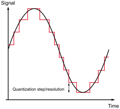
The resolution (in bit)
- The higher the resolution of a digitally operating sensor, the finer analogue signals can be processed. Analogue output curves from digital devices therefore always have a fine step (staircase). The height of these steps is determined by the resolution of the sensor.
The update rate (in microseconds [µs] or milliseconds [ms])
- Signals from digitally working sensors are always transmitted with some time delay.
If this information can be found on an encoder datasheet, it is an indication that the encoder processes data digitally. A detailed description of the meaning of these values and example calculations can be found in the absolute encoder guide.
Protection against environmental influences / IP protection
IP stands for Ingress Protection. The IP grade specifies the measures taken to protect the shaft bearings, housing and electrical connections of a product against the ingress of solids and fresh water. The correct formal term is the IP protection class of a product.
The consideration of liquid protection only applies to fresh water. All other media such as oils, salt water, suspensions, alkalis or acids are excluded.
The IP specification consists of two digits, which are followed by the two letters "IP":
- First digit: Protection against penetrating particles
- Second digit: Protection against ingress of fresh water
Fully sealed ETx25K Hall kit encoder: Attention, the magnet is exposed. Sealing applies to electronics and housing only.
Distinction of IP protection
Shaft side, rear side or IP protection of the electrical connection
For contactless angle encoders, in addition to the overall value of the product, a distinction is made between IP protection on the shaft side, IP protection on the rear side and IP protection of the electrical connection. However, in the case of an electrical connection cable with tinned cable ends, the cable ends are excluded from IP protection.
IP protection observed with one shaft in motion and at standstill
For angle encoders with their own shaft bearing, a distinction is often made between the degree of protection for the shaft in motion and the shaft at rest. In these cases, the information is defined by the letters "M" for movement (shaft in motion) or "S" for stop (shaft at standstill) following the IP protection numbers.
A higher shaft-side IP protection for a stopped shaft may be relevant if the encoder is part of an application/plant that is only cleaned when the plant is stopped.
Electrical connections
Supply voltage
All non-contact angle encoders require a direct voltage (DC) supply (VSUP) to operate. A distinction is made between encoders where the supply voltage changes within a defined range when
- there is a ratiometric relationship to the output signal
- no ratiometric relationship exists, i.e. has no effect on the output signal
With a ratiometric relationship between supply voltage and output signal, the output signal changes in the same multiplicative ratio as the supply voltage. This option is only available for absolute encoders with analogue signal output.
Furthermore, not all available supply voltage ranges can be combined with all output electronics. When selecting the supply voltage, check that the required output circuitry is available for the desired supply voltage. Refer to the encoder datasheet for possible combinations.
Redundancy
Some applications require sensor signal redundancy. Redundant encoders are often used for the following reasons:
Increase system availability
- The dual sensor design reduces the likelihood of system failure. If either line fails, a fault is logged. However, the machine or plant can continue to run until the next maintenance interval when the sensor can be replaced without loss of machine time.
Increased operational safety
- When operating safety-critical machinery (e.g. vehicles, aircraft, etc.), failure can be fatal. Redundancy provides a safe, controlled shutdown of these machines or systems until the sensor is replaced. Redundancy is mandatory for many of these applications.
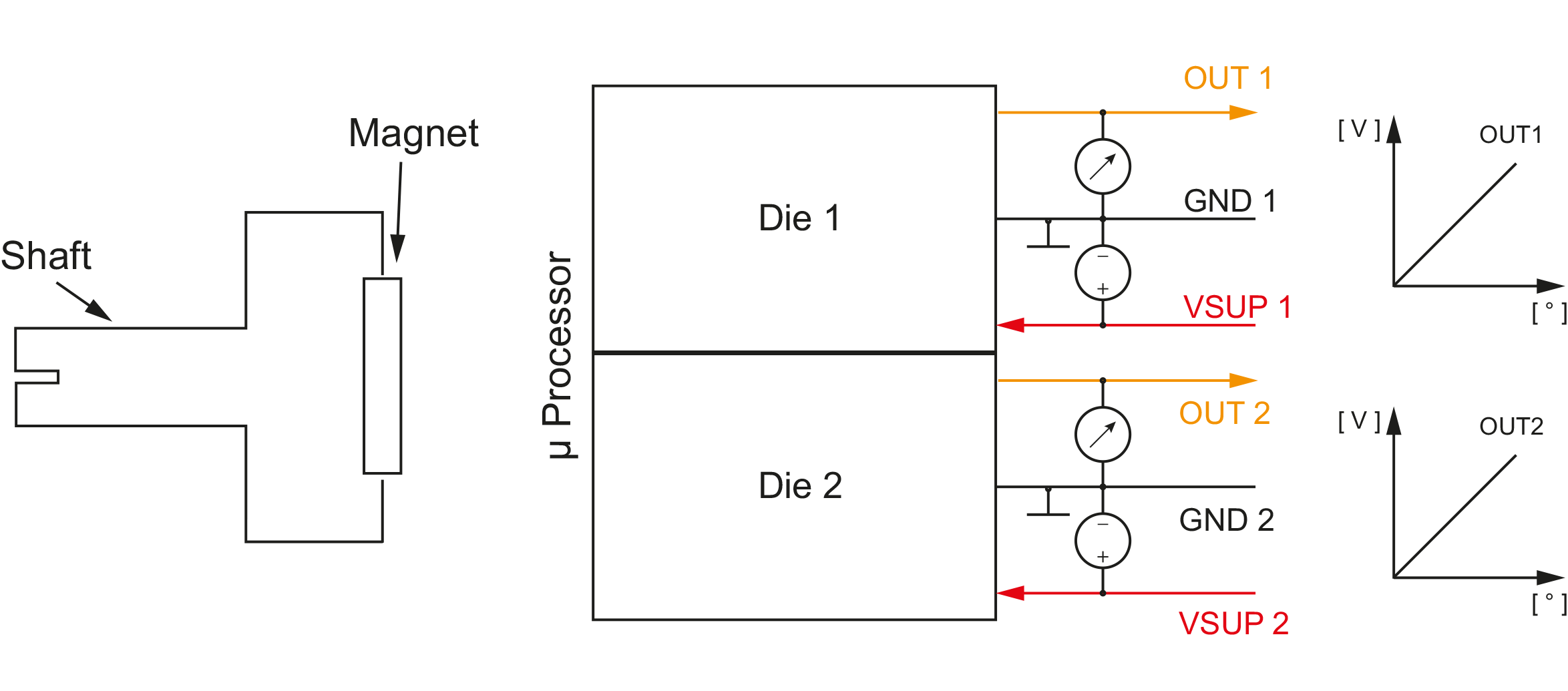
If it is not possible to install two encoders in principle, it is possible to implement encoders with two separate supply voltages and a separate ground (GND) for the operation of the encoder, providing a galvanically isolated additional electronics.
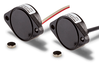
- With magnetic encoders, the magnet is always at the end of the shaft. It is therefore not possible to run the shaft through the housing to another sensor. The magnetic sensing element itself is double/redundant and, on some models, galvanically isolated as an option.
- With optical encoders, it is possible to produce tandem versions that share only the shaft mechanically, but are otherwise completely duplicated.
Signal outputs
For contactless absolute encoders, the following signal outputs are available.
Analogue:
- Voltage output (different ranges, ratiometric, non-ratiometric)
- Current (0...20 mA, 4...20mA,...)
- Pulse width modulation (PWM)
Digital:
- SPI: Serial Peripheral Interface
- SER: Special form of the SPI format
- SSI: Synchronous Serial Interface
For contactless incremental encoders, the following output circuits are available:
- OC (Open Collector, Pull Up resistor not integrated in encoder)
- Voltage Output (Open Collector circuit incl. pull-up resistors integrated in the encoder housing)
- TTL (Transistor Transistor Logic)
- PP (Push Pull)
- Linedriver
Cabling
Cable lengths and tolerances
Electrical lead tolerances for angle encoders are different to those for encoder housings and shafts. Note: If the cable tolerances are not explicitly stated in the data sheet, the IPC / WHMA-A-620 applies:
| Cable length | Permissible tolerance of the connection cable (incl. plug) |
| ≤0.3 m | +25 mm -0 mm |
| >0.3 m...1.5 m | +50 mm -0 mm |
| >1.3 m...3 m | +100 mm -0 mm |
| >3 m...7.5 m | +150 mm -0 mm |
| >7.5 m | +5% -0% |
Cable Shield
For MEGATRON angle encoders with metal housing, the connection cable is shielded by an external cable shield. With all angle encoders in a plastic housing, the connection cable is not shielded.
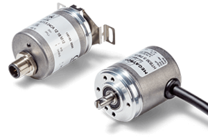
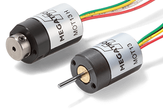
Designs of rotary encoders
Encoders are offered in a variety of housing styles. They can be divided into kit encoders (without shaft bearings) and encoders with shaft bearings. The latter are available with either plain or ball bearings and with solid or hollow shafts.
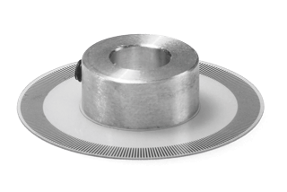
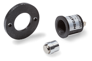
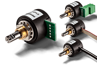
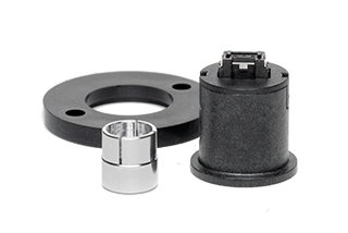
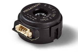
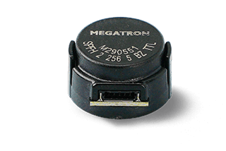
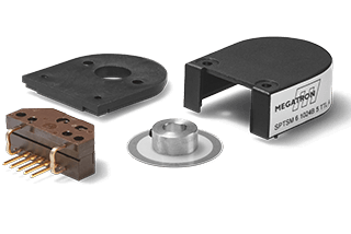
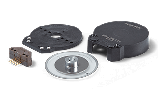
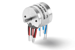
Kit-Encoder
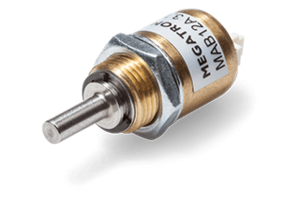
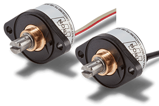
MAB12AH series magnetic kit encoder
Kit encoders have no shaft and therefore no shaft bearing. For these encoders, the term "encoder with external shaft bearing" is also used because the bearing is not part of the encoder. With magnetic encoders, a magnet is attached to the end of the shaft, and with optical kit encoders, the encoder disc is attached to the shaft in the application. Kit encoders are suitable for high speeds up to many thousands of rpm and are virtually free from mechanical wear.
Due to the lack of mechanical connection between the magnet and the encoder, the following decouplings can be realized:
- Mechanical decoupling
- Galvanic decoupling (no electrical potential reference between shaft and encoder)
- Thermal decoupling
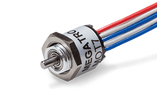
Encoders with bearing - "shaft encoder" and "hollow shaft encoder"
These encoders have their own shaft bearing. A distinction is also made between two designs: Solid shaft encoders (often referred to simply as "shaft") and hollow shaft encoders.
The versions with solid shaft are also called shaft encoders. For shaft encoders, the term "angle encoder with integral bearing shaft" is also used.
Hollow shaft encoders, as the name suggests, do not have a solid shaft. An application-side shaft is inserted into the hollow shaft and fixed to it. In through-hole versions, it is even possible to push the shaft completely through the encoder, which can then be freely positioned axially.
Installation and mounting
The possibilities for mechanical mounting of the encoder in the application depend on the design of the encoder housing. MEGATRON offers a total of five different mounting options for its contactless encoder families. The mounting can be done by
- Bushing
- Flange
- Threaded holes
- Synchro flange
- Mounting ring
- Spring plate
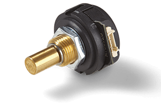
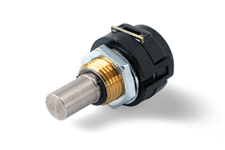
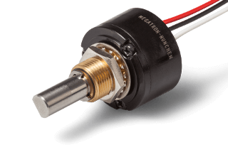
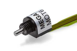
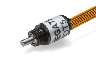
Central thread and union nut (bushing)
The central thread version is a very simple and quick mounting method. To mount an encoder with bushing, generally only a single hole needs to be drilled in the mounting plate of the application. The encoder bearing bush is inserted through this hole until the face of the encoder housing or the surface of the locating collar is in contact with the mounting plate. Finally, the encoder is secured to the mounting plate using a union nut and shim/lock washer. The nut and washer are often supplied with the encoder.
Some encoder families also have an anti-rotation pin. This prevents unintentional rotation of the encoder housing about the central axis when the coupling nut is tightened. An additional second hole must be drilled in the mounting plate for this anti-rotation pin. The anti-rotation pin (if fitted) also acts as a zero reference (0° position).
To mount the encoder in a mounting plate, the hole pierces the mounting plate completely. This can allow liquids and dust to penetrate from the front to the back of the mounting plate. To prevent this, an optional gasket is supplied to be inserted between the front of the encoder and the mounting plate. This seal is an option for the ETx25 family of encoders, for example.
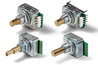
Absolute encoder series ETA25 with central thread (bushing)
Flange mounting
Flange mounting is a widely used, simple mounting method that prevents the encoder housing from twisting around the centre axis during mounting. To mount the encoder, three holes must be drilled in a mounting plate in the application. One hole is required for the centring collar or thread, and two more are required for screw mounting of the encoder. The mounting screws are usually not supplied with the encoder.
Threaded hole mounting
Threaded hole mounting is a very secure method and is based on commercially available standard parts. To mount such encoders, a minimum of three holes must be drilled in a mounting plate in the application: One hole for the centring collar and two additional holes for mounting the encoder. A threaded hole in the encoder housing serves as a 0° reference. Mounting screws are not normally supplied with the encoder.
Servo flange mounting
This method of mounting allows the zero point (reference point) to be subsequently changed by rotating the encoder housing, and is therefore particularly useful for absolute encoders. A minimum of four holes must be drilled in a mounting plate for mounting.
- A hole for the centring collar that fully penetrates the mounting plate and
- three additional holes at the rear of the mounting plate for screwing on the clamps, which do not have to penetrate the mounting plate.
The synchro clamps are not supplied with the encoder and can be ordered as accessories from MEGATRON. The clamps are used to secure the encoder to the mounting plate by means of contact pressure. The fourth threaded hole in the encoder housing serves as a zero point reference (0° reference).

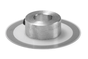
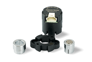
Mounting by means of a mounting ring
This mounting method is restricted to encoders without shaft bearings (kit encoders). For mounting, at least three holes must be drilled in a mounting plate: One hole for the centring collar, which must penetrate the mounting plate completely, and at least two additional holes on the back of the mounting plate for fixing the mounting ring, which do not have to penetrate the mounting plate. If the encoder is initially fitted loosely with the mounting ring, this allows the encoder to be rotated about the central axis to align the zero point (i.e. particularly useful for absolute encoders). The position is then fixed simply by tightening the screws.
MAB12AH series kit encoder with mounting ring
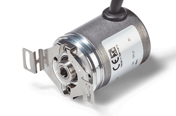
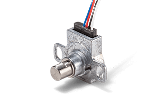
Spring plate assembly
This mounting method is only used for hollow shaft encoders. The advantage of this method is that mechanical influences on the encoder caused by radial and axial eccentricities of the application-side shaft can be minimized, thus reducing the load on the bearing. This mounting method requires a minimum of 2 holes to mount the encoder.
Product customization
For over 60 years, MEGATRON has been a reliable partner for your design-in. In addition to the wide range of options available for our sensors, we also offer specific designs, even in small quantities, that are tailored exactly to your application requirements. Whether you are in the early stages of a project or in series production, we are here to support you.


Encoders are sensors that use electronics to capture angular information in an application and convert it into electrical signals. Optoelectronics and advanced technologies based on Hall effect sensors provide excellent measurement results. In addition, the non-contact measuring principle means that the sensors have a particularly long service life. A wide range of electrical signal outputs, connections and encoder designs means there are many options to suit your application.
A key feature is the range of angles that the encoder can detect. Single-turn encoders cover angles up to 360 degrees, while multiturn encoders cover angles above that. There is also a difference between absolute and incremental output. Environmental considerations and ease of service are also important in choosing the right product.
Among all the possible parameters, each sensor technology has its own advantages and each sensor has its specific characteristics, which we will be happy to work out together with your application requirements as part of our consultancy. In demanding applications, technical product adaptations are often required. MEGATRON is your specialist for these cases and offers the best technical and economical solutions. As a long-term, reliable partner, we will support you from the initial enquiry, through series production, right up to the "end of life" of your application with high delivery reliability and guaranteed product quality.