 EN
EN DE
DE ES
ES FR
FR PT
PT IT
IT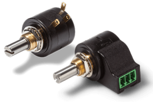
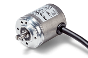


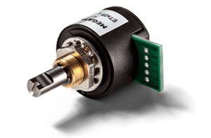
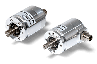
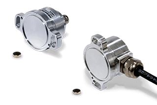
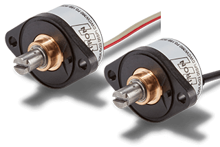
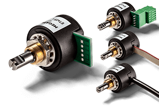
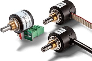
Absolute Encoders
Magnetic rotary encoders for absolute angle measurement
Guide Absolute Encoders
Index
What is an absolute encoder?
Absolute encoders are rotary encoders that measure angles, convert this information into electrical signals and output them as absolute values. The use of electronics to process the measured value distinguishes them from potentiometers, which also provide absolute values but are passive components without integrated electronics. Absolute encoders have a fixed reference point for angle measurement to which the output value is always referenced. The principle of an absolute encoder is fundamentally different from that of an incremental encoder, for example, where only angle changes (relative values) are transmitted by the encoder.
Absolute encoders are divided into two categories according to the angular range to be measured. Encoders that measure angles over several revolutions are called multiturn encoders, and encoders that measure angles up to 360° are called singleturn encoders.
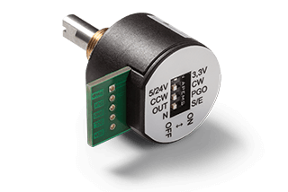
Signal programming of absolute encoders
Absolute encoders offer a wide range of options for displaying the measured angular values as an electrical signal function at the output. The electronics of many encoders are programmable, allowing the output waveforms to be customized. The following example shows the standard factory programming of an analogue absolute encoder:
The encoder is programmed in the CW direction of rotation with an output signal of 0...10 V (when the shaft rotates clockwise) and measures an angle of 0...360°.
When it is at 0°, it outputs 0 V. When the shaft is rotated 90° clockwise, it gives a value of 90°/360° * 10 V = 2.5 V. This value remains constant as long as the encoder shaft is not moved. The figure in example 1 shows the signal curve of such an absolute encoder.
| Measured angle [° degrees] | Output voltage [Volt] |
| 0° = 0 V | 0 V |
| 360° = 10 V | 10 V |
| 45° = 1.25 V | 1.25 V |
| 90° = 2.5 V | 2.5 V |
| 180° = 5.0 V | 5 V |
The term "Full Scale" is often used with the abbreviation "F.S." to refer to the entire signal output scale. In the example above, F.S. = 10 V. Without knowing the maximum voltage, programming can also be done using percentage values. For example, 0° corresponds to 0% F.S. (0% of the maximum value, i.e. 0 V) and 360° corresponds to 100% F.S. (100% of the maximum value, i.e. 10 V). In this way, a signal output function can be accurately described without the use of a graph:
0° = 0% F.S.
90° = 100% F.S.
180° = 100% F.S.
270° = 0% F.S.
360° = 0% F.S.
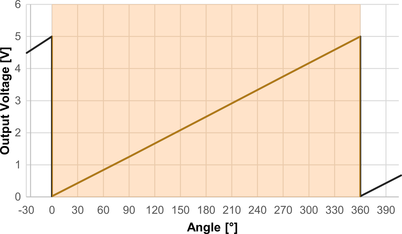
Example 1
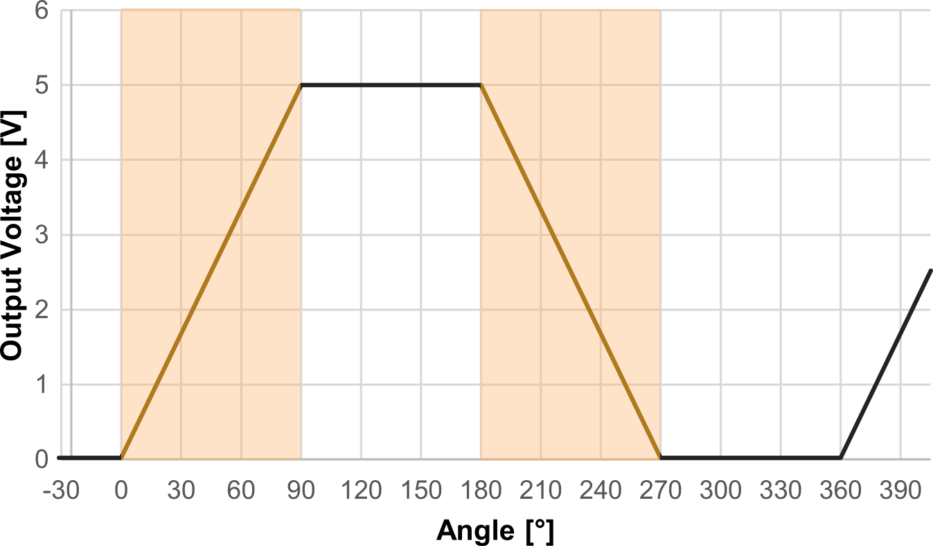
Example 2
The figure shows the signal curve for these requirements in example 2. The output signals of absolute encoders can also be output via other interfaces, e.g. as output current or by pulse width modulation (PWM).
Hall effect encoder
The Hall effect is a phenomenon in which an electrical voltage is generated in a current-carrying conductor (Hall element) when it is in an external magnetic field.
The effect is shown in the diagram opposite and can be explained as follows: When current flows through an electrical conductor, charge carriers (electrons) move through the conductor. If an additional magnetic field is applied, e.g. by an external magnet, the charge carriers are deflected perpendicular to the direction of the current. This is called the Lorentz force: It deflects charge carriers when they move and when an external magnetic field is applied. The electrons now accumulate at the edges of the conductor. The charge separation creates an additional voltage perpendicular to the direction of the current, called the Hall voltage.
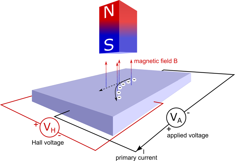
A magnetic field generates a Hall voltage in a current carrying conductor
If the external magnetic field changes as the magnet moves, the Hall voltage also changes - making it relatively easy to implement sensors. For example, if a circular, diametrically magnetized (north pole/south pole) permanent magnet is placed over a Hall element and the magnet is rotated, a sinusoidal output voltage curve can be measured. If the position of the magnet does not change, the measured value remains constant. However, a Hall sensor can only work if a current is flowing, otherwise the Lorentz force will not work. Therefore, Hall sensors require current during operation, even if the measurement position does not change.
Gradient based Hall sensors
In principle, external magnetic fields can interfere with Hall technology if no precautions are taken. Today, so-called gradient-based Hall sensors are used, which are largely insensitive to such interference.
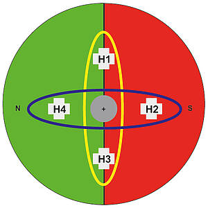
The principle of this particular variant is that two or more Hall sensors are placed close to each other. The measuring magnet, which is very close to these two sensors, creates a difference in the signals of the two sensors because the curvature of the field is relatively strong. However, an external interfering field, which usually has a slight curvature, is 'seen' by both sensors in the same way. If only the difference between the two sensors (the gradient) is evaluated, then virtually only the measurement magnet is perceived and the measurement system is therefore very robust to external interference fields.
Resolution
Most Hall encoders are digital encoders and process measurement signals with a certain resolution. The information is processed with an accuracy corresponding to the number of bits. The higher this value is, the finer the signals can be processed. Analogue output curves from digital devices therefore always have a fine gradation, the height of which is determined by the resolution. Typical resolutions are 10 bits, 12 bits or 14 bits, depending on the encoder model. For example, the angular resolution is 0.088° for 12 bits and 0.022° for 14 bits. The following simple observation helps to determine these values:
- The resolution is used to calculate the number of state changes that can be displayed: 1 bit corresponds to 2 state changes (since 21 = 2), 12 bits correspond to 4096 state changes (since 212 = 4096)
- The number of state changes is divided over the entire range of the electrical angle of rotation
To calculate the angular resolution, the effective electrical angle of rotation must be divided by the number of possible states:
\(\text {Angular Resolution in degrees} =\frac {360°} {2^\text {number of bits}}\)
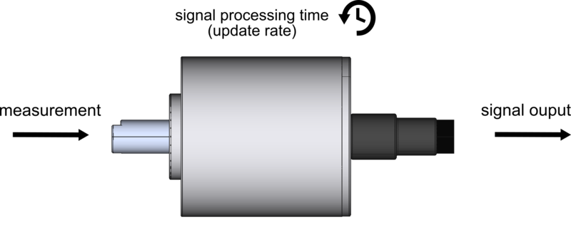
Update rate
Since many Hall encoders are equipped with digital integrated circuits (ICs) that always send their signals with a certain delay, the update rate in milliseconds must be taken into account in the application. The update rate is the time between the acquisition of the measured value and the output of the signal in the angle encoder. It is usually between 96 µs and 600 µs for magnetic encoders with digital signal processing, but can be up to 3 ms for some multiturn encoders.
If the update rate is increased, this results in a higher current consumption of the angle encoder. Some angle encoders can also be ordered with a reduced update rate, for example 600 µs instead of 200 µs, to reduce power consumption. These angle encoders are then particularly suitable for use in a battery-powered application with low power consumption.
If a different update rate of the angle encoder is required, it must be ordered ex works. This feature cannot be changed in the field. The update rate should not be confused with the sampling rate.
Accuracy - Absolute linearity
Calculating the possible angular deviation of an encoder is complex and depends on many factors, such as environmental influences (temperature), mechanical factors (bearing play), component tolerances of the electronics, etc. In order to determine the angular error of an absolute encoder reliably and quickly, a calculation based on absolute linearity has proven to be practical. Absolute linearity describes the maximum possible percentage deviation of the signal output function (the measurement result) from an ideal straight line. However, these specifications apply under the following conditions:
- Operation of the shaft in one direction of rotation
- Operation at room temperature
- Reference to an electrically effective angle of rotation specified in the data sheet
- The absolute linearity is a "worst case" consideration
- In practice, the actual angular error will be lower
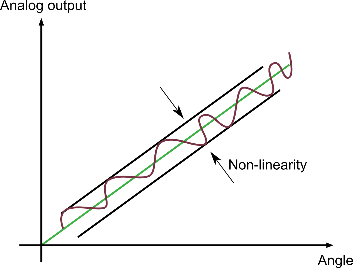
Absolute linearity describes the deviation of the signal (red) from an ideal straight line (green) passing through the zero point.
The angular error is reproducible for the individual encoder. This means that for a given angle of rotation, the error will always be approximately the same. The high repeatability of a contactless absolute encoder therefore allows the signal output function to be offset against a calibration function stored in an evaluation unit in order to reduce the angular error of the encoder. The absolute linearity information is a fixed value in the datasheet of absolute encoders.
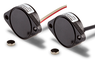
The absolute straight lines information in the datasheet of a kit encoder (without shaft) is given under the condition that the centre axis of the magnet is aligned with the centre axis of the encoder. Some magnetic kit datasheets also give information on how the absolute linearity value changes when the magnet is positioned eccentrically to the centre axis.
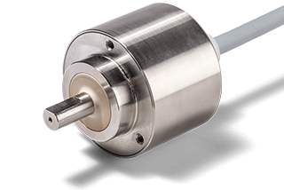
Singleturn and multiturn absolute encoder
Singleturn absolute encoder
Singleturn encoders are absolute encoders and are only suitable for measuring angles ≤ 360° because their output signal is the same as 0° after one full revolution. Most non-contact singleturn absolute encoders therefore measure an angle range from 0° to a maximum of 360°. This category also includes models with a limited angular range, such as ±45°.
Multiturn absolute encoder
Multiturn encoders are capable of measuring angles beyond zero, i.e. beyond 360°. This is possible because the measuring system is capable of counting the number of revolutions. Often the signal increases continuously over the entire specified angular range. MEGATRON's ETA25PM multi-turn absolute encoder, for example, is capable of measuring angular ranges up to a maximum of 72000° (up to 200 shaft revolutions) and this range can be limited by programming. The factory setting is 3600° (10 revolutions). When measuring angles >360°, however, the sensor may be rotated by a maximum of ±179° in the de-energized state, otherwise the sensor will lose its measured value.
To avoid this, there are true power-on encoders. They have the ability to output the correct angular position in any case, even when no power is applied. A possible variation is to use a gear reduction so that the shaft rotates several times, but the magnet only rotates a maximum of 360° within the positioning range. See our Multiturn Encoder Guide for more information on this topic.
Electrical signal outputs
Analogue and digital signal outputs are available for the absolute encoders.
Analogue signal outputs for absolute encoders:
- Voltage
- Current
- PWM (pulse width modulation)
Digital signal outputs for absolute encoders:
- SPI
- SSI
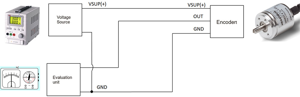
Current and voltage output
Analogue outputs are still very important in the encoder market. For this reason, most series are offered with these outputs. Absolute encoders from MEGATRON with analogue signal outputs are always designed in 3-wire technology, unless they offer redundancy. The two connections for the supply voltage (VSUP) and the output signal (OUT) have a common ground. Many contactless absolute encoders with redundant signal outputs are galvanically isolated and therefore offer separate supply voltages, ground and signal outputs for each signal branch.
External wire break detection
In order to generate an external wire break detection via an evaluation unit, the output signal of the angle encoder must not be zero during operation, regardless of the angle, as 0 V output voltage or 0 mA output current are the indicators of a wire break. For all MEGATRON absolute encoders with current output, an external wire break detection can be realized by factory programming, as the measured angle is always output in a range of 4...20 mA.
For a voltage output, we have series in our programme that offer this function ex works. However, this is not possible on all models. Please contact us if you are not sure.
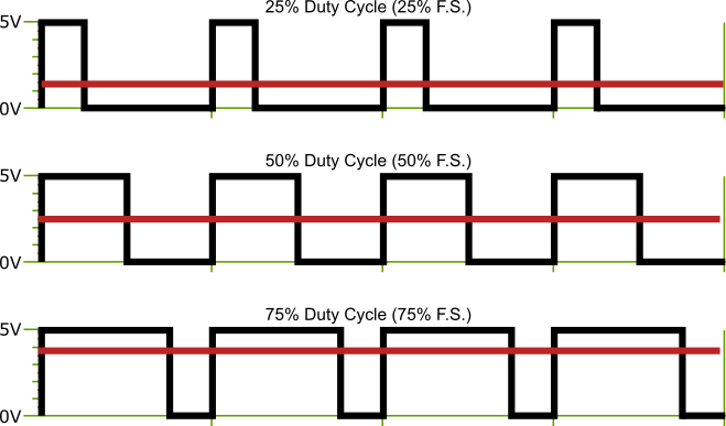
PWM interface
With the PWM output, the measured angle is not proportional to the signal amplitude but to the pulse width. The advantage over current or voltage outputs is that this form of signal output is largely insensitive to electromagnetic interference (EMI), since EMI usually affects the signal amplitude rather than the frequency (e.g. AM/FM radio). However, the signal must be detected in an external evaluation unit designed for PWM.
The pulse width on MEGATRON encoders varies between 10% (0% F.S.) and 90% (100% F.S.). The carrier frequency is 244 Hz.
Digital interfaces
Microcontrollers often provide inputs for digital signals based on the SPI and SSI formats. Absolute encoders are offered with these digital interfaces to ensure high compatibility with many microcontrollers on the market. It is beyond the scope of this manual to describe the digital interfaces and their specific characteristics in detail. The following explanation is therefore only intended as a brief overview.
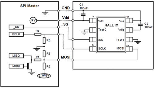
SPI (Serial Peripheral Interface)
The SPI interface is based on a serial master/slave BUS protocol developed by Motorola. Communication is via the data lines:
- MOSI (Master Out → Slave In)
- MISO (Master In ← Slave Out)
- SCK (Serial Clock) (= bus clock/shift clock)
In addition to these three lines, a line called "Slave Select (SS)" or "Chip Select (CS)" is required for each slave. Please note that this format is not suitable for field communication as the cable length between master and slave should not exceed 0.6 m. For further information on MEGATRON magnetic encoders with SPI interface, please contact us.
SSI (Synchronous Serial Interface)
The SSI interface is a widely used interface for serial data communication. It is particularly suitable for the digital communication of absolute encoders in the field, where measured values have to be transmitted over long cable lengths between the encoder and the evaluation unit. The data transmission (clock and data) is carried out via four lines, each of which carries two signal pairs (symmetrical signal transmission in phase and 180° in phase). If the signals of one signal pair are superimposed by a disturbance on the transmission path between slave and master, this disturbance can be removed from the two signal pairs in the evaluation unit by subtraction. Twisted pair signal cables with individually shielded pairs are particularly suitable for reliable transmission of measurement signals over long distances. For further information on SSI communication with MEGATRON encoders, please contact us.
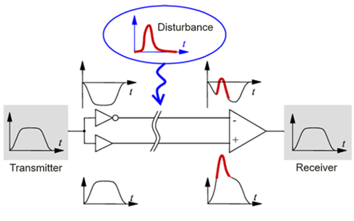
Concept of fault elimination using SSI
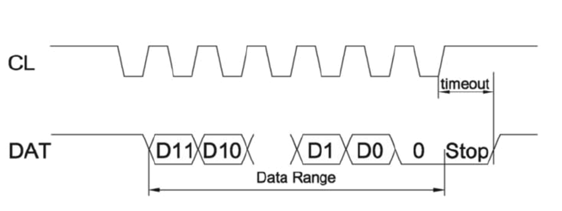
Data transmission on the two channels Clock and Data


Absolute encoders are rotary encoders that measure angular positions in an application, convert this angular information into electrical signals and output them as absolute values. Magnetic sensor technologies based on the Hall effect provide excellent measurement results, with the well-known advantages of non-contact measurement and virtually unlimited sensor life.
The wide choice of electrical output types, connections and mechanical designs provides reliable, repeatable and accurate measurement data for almost any application. The angular measurement range of an absolute encoder is of key importance. Singleturn encoders cover angular ranges up to 360 degrees, and multiturn encoders cover angles beyond that. Particularly noteworthy is the ability to program custom output characteristics.
And by taking all possible parameters into account, we work out the best possible product solution as part of our consultation. In many cases, demanding applications require technical product adaptation. MEGATRON is your specialist for such cases and will support you as a long-term, reliable partner from the initial enquiry to the realization of series production and beyond to the "end of life" of your application with assured quality products and high delivery reliability.