 EN
EN DE
DE ES
ES FR
FR PT
PT IT
IT
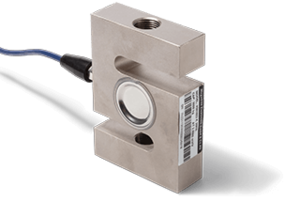


Load Cells
Shear beams, button load cells and S-Beam force transducers with strain gauge measurement technology
Guide for Load Cells
Index
How force transducers work

Force transducers consist in their measuring chain for force application of a mechanical deformation body, a mechanical-electrical converter (sensor element) and a subsequent electrical amplifier for processing the measured signal.
The way in which all force transducers work is basically the same, and metaphorically speaking, a bending spring (deformation body) best illustrates the principle: A force is applied to a deformation body, creating areas of compression and tension. Sensor elements are mounted on this body to detect these changes in shape, convert them into electrical signals and transmit them for processing. In order to achieve an almost exact result, the deformation paths must be kept as small as possible.
Depending on the application and the forces to be measured, the following deformation bodies are used in the construction designs
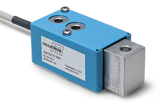
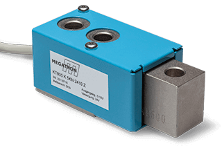
- Shear beams
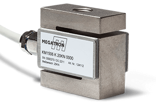
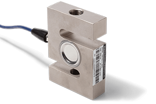
- S-Beams
- Load cells
Design and materials determine the characteristics of a force sensor and, in particular, the nominal force.
Strain gauge sensor technology
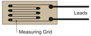
In a force transducer, the sensing element is critical to the quality of the measurement chain, as it is the element that is subjected to compression and tension as the force is applied. However, only a small part of a force transducer is actually the force sensor. In order to detect the forces, sensor elements, known as foil strain gauges, are attached only to certain points on the deformation body. These strain gauges (mechanical-electrical transducers) convert mechanical tensions and compressions in the deformation body into electrically measurable signals. The strain gauges consist of a wafer-thin metallic resistance grid and an insulating carrier foil is bonded to the measuring body in a Wheatstone bridge circuit (four strain gauge elements) at the calculated tension and compression zones: two elements detect the tension, two the compression that occurs. The strain gauge elements are powered by a supply voltage. When the measuring body is subjected to tension/compression, the resistance in the strain gauge grid changes and consequently the output voltage.
As the resistance changes are in a few mV/V ranges, the voltage signal is processed in the following amplifier circuit for further processing.
Advantages of the strain gauge technology:
- Very high accuracy
- Very high robustness
- Very well suited for dynamic load changes
- Very high long-term stability
- Proven technology
Wheatstone bridge circuit
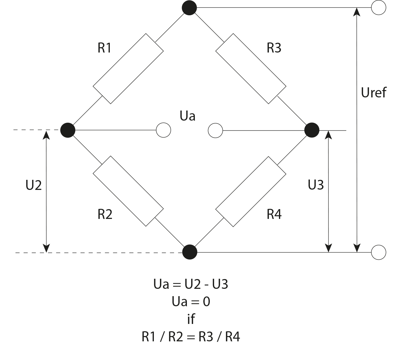
With an unloaded measuring body in a balanced strain gauge bridge circuit, the output voltage is zero volts. Since a measuring body reacts to temperature changes with tension and compression, for example, the Wheatstone bridge circuit suppresses these temperature effects very well. Apparent strain has little effect on the zero point in this type of circuit. Since the magnitude and direction of each of the two pairs of strain gauges (one pair for compression / one pair for tension) undergo an almost identical change in resistance, there is almost no change in the resulting output signal. Also, unwanted mechanical bending moment or shear force influences diagonal to the measuring direction compensate to some extent for the symmetry of the strain gauge bridge circuit.
The output voltage Ua is zero if the resistance ratio of both bridge branches is equal. When these resistance ratios are present, the bridge is said to be balanced. Ua is of the order of a few millivolts [mV], so the electrical signals are expressed in the unit millivolt per volt [mV/V].
Measuring amplifier (integrated or external) and calibration
Of particular note are our KT versions. These transducers are offered with an integrated amplifier in the sensor housing and are factory calibrated. This eliminates the need for wiring between the force sensor and the amplifier, as well as time-consuming tuning between the sensor and the amplifier. A stable signal is obtained in one unit, otherwise in the mV/V range.
All transducers with built-in electronics or with standardized output are factory calibrated in the required force direction in Newtons. The zero point and sensitivity are adjusted according to the specified mounting position (upright or suspended) or load direction (compression or tension).
External amplifiers such as our IMA2DMS are therefore offered for sensors without integrated amplifiers.

KT Types with amplifier

External Amplifier
Mounting instructions
Some important basic rules must be followed to ensure the correct and safe installation of force transducers.
Force introduction: Always apply and dissipate forces vertically and precisely
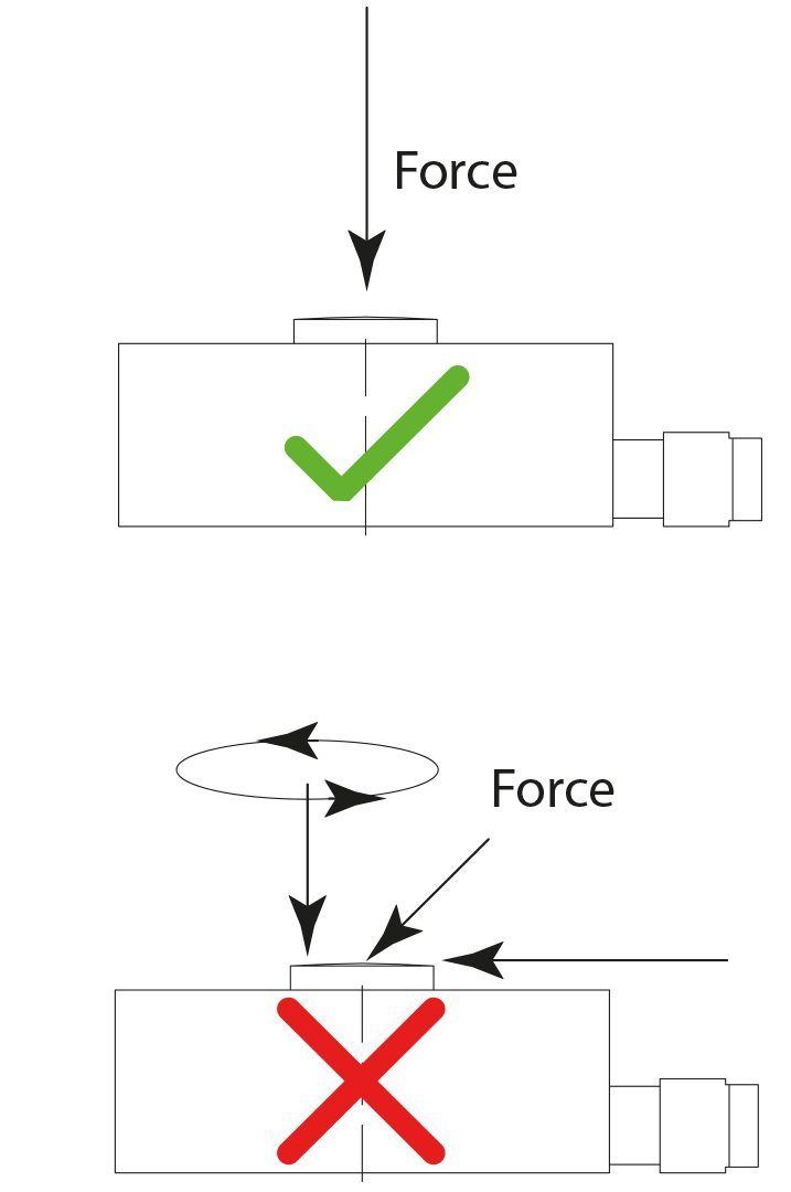
The load must be applied as accurately as possible in the direction of measurement of the load cell. In this way the applied load and the load cell form a continuous line of action. For composite loads, the actual line of action of the force (resulting force vector) must be determined and the transducer aligned accordingly. Components that act differently, such as eccentric loads, lateral forces or torsional moments, are disturbance variables and falsify the measurement signal. In addition, the spring body may be irreversibly deformed. Deformation or mechanical adjustments (e.g. drilling holes in the measuring body) must not be carried out!
Crash, overload and breakage protection:
When designing devices for force measurement, the specified nominal force must be strictly adhered to in order to exclude measurement uncertainties or, in critical cases, avoid destruction by irreversible deformation of the force transducer.
If the mechanical design of a force measuring device cannot exclude the possibility of an overload occurring in a critical case, appropriate devices shall be installed to protect the force sensor. For example, supports may limit the strain range of the deformation body in the case of compressive forces.
Special attention should be paid to the suspended mounting position of a load cell that is subject to tensile forces. In the case of suspended loads, precautions must be taken to secure the load (e.g. by chains or suspension ropes mounted parallel to the load cell). Otherwise, in the event of overload, the load cell may "break/tear" and the load may fall.
Surface properties: Stable and solid bearing surface
Especially for load cells, the measuring body must be installed on a solid platform according to the mounting instructions. Bending of the baseplate must be avoided. The substructure provided for mounting should be sufficiently large and have as flat a mounting surface as possible.
Creating a structurally stable measuring chain
The load carrier, force application components and the force transducer must be connected rigidly, i.e. without play. In the case of movable mounting positions, in particular also in the case of suspension mountings in the direction of traction, rod ends or ring nuts must be used for force application. In the case of multi-axial degrees of freedom, a cardanic mounting should be used to avoid measurement uncertainties and destruction of the transducer by impermissible transverse and lateral forces.
Tensile and/or compressive force
Force transducers are preferably used in one direction of loading, either tension or compression. Only S-Beams are suitable for alternating loading. Shear beams and load cells can usually only be loaded in compression (take a look at the data sheet for the application of force). Force sensors with integrated electronics are only calibrated in one direction, either in tension or in compression.
Avoid shock and vibration
Shocks and vibrations affect the measurement result of a force transducer (force F = mass "m" x acceleration "b"), e.g. by superimposition in static measurements. The dynamic forces involved must be taken into account when designing the measurement ranges and overloading of the transducer due to dynamic load changes must be avoided. The resonant frequency of the various deformable bodies depends, among other things, on their mass and stiffness (mechanical impedance). A vibrating load must be well below this resonant frequency in its frequency range.


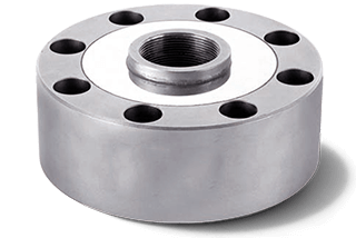
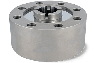

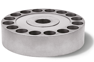


Load cells convert applied forces into electrical signals. Depending on the direction of the force, a metal spring body is expanded or compressed, which is detected electrically by sensor elements and transmitted for signal processing. Our force transducers are all based on proven strain gauge full bridge technology and provide an analogue output signal in mV/V.
The forces applied to the measuring body must not exceed the maximum rated force for which a load cell is designed. The nominal force is determined by the stiffness of the measuring body. The stiffness of the measuring body is determined by both the design and the material.
We offer a wide range of standard load cells for small loads up to several hundred kilonewtons. Our many years of experience and extensive application know-how are available to you for the optimum design-in of special measurement tasks, even for small quantities.