 EN
EN DE
DE ES
ES FR
FR PT
PT IT
IT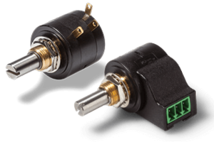

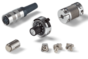


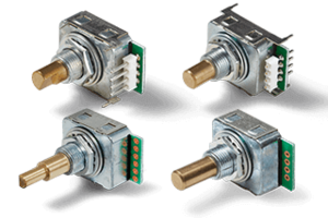
Panel Encoders
For manual control with incremental interface
Guide optical Panel Encoders
Index
5 tips on the way to the right panel encoder
When selecting the appropriate panel encoder, the user must be clear about the basic requirements he or she has for the product.
1. Haptic and mechanical requirements are:
- With or without detent
- The actuating torque
- The detent torque
- The actuating force on the pushbutton
- The sensing travel
- With end stop, without end stop
- The shaft diameter
- The sensor mounting in the application
2. The primary electrical requirements include:
- The supply voltage
- The current consumption
- The output signal, the output electronics
- An electrical redundancy
- With push button [yes/no]
- Max. voltage/current of the push-button
3. Environmental characteristics:
- The operating temperature
- The IP protection level
- Resistance to shocks/vibrations
4. Lifespan:
- Number of shaft actuations
- Number of push button actuations
5. Price:
- Upper price limit of the manual adjuster
- Upper price limit for the knob
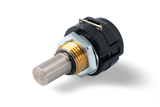
What is an optical manual encoder?
Optical manual encoders belong to the incremental encoders (see the guide). However, they are also mainly used as setpoint devices by hand. In this case, setpoints are output as electrical signals in the form of increments by means of a manual rotary movement of the encoder axis (clockwise or counterclockwise). Our portfolio includes only encoders with optoelectronic sensor principle. They may have additional features such as integrated push buttons and/or so-called detents. If a push-button is integrated, a switching contact is closed when axial force is exerted on the shaft. With the detent option, the torque changes in equidistant steps when the shaft is actuated.
Popular applications are:
- Changing the volume, for example in AV receivers, CAR audio systems
- Scrolling through menus
- Specification of numerical values
- Confirmation of a function or setpoints
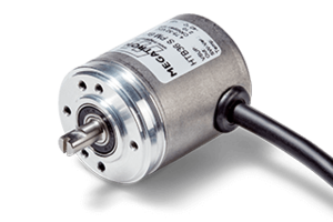
Optical scanning principle

Optical incremental encoders supply their useful signal in the form of pulses. To detect the direction of rotation, the encoders provide two electrical signals at the output, those of channels A and B, whose signals are phase-shifted by 90°. An evaluation unit uses the relationship of signals A and B to detect whether the axis of the encoder is rotated clockwise or counterclockwise. The optical sensor technologies have several advantages. It is a contactless measuring principle, i.e. the measured value transmission between the measured value recording and the measured value acquisition takes place without contact. For more details on optical incremental encoders, see their guide.
Push button switch
Many encoders can be ordered with an integrated push button switch, which is actuated by an axial force (pressure) acting on the shaft. The switches work exclusively as normally open (N.O.) contacts. This means that the switching contact is closed during operation and open when not operated. The switching function is implemented by means of a switch/snap-action switch under the shaft.

The following selection criteria must be observed for the permissible electrical characteristics of the push button:
- Maximum permissible voltage applied to the push button
- Maximum permissible current flowing via the push button
- Contact resistance of the push button
- If the push button has a ground reference or not
Most of the parameters vary depending on the encoder, whereby the maximum permissible voltage of the push button is 12V/DC for all MEGATRON encoders.
The following selection criteria must be observed for the mechanical characteristics of the push button:
- Lifespan (number of actuations)
- Travel [mm]
- Actuating force [N]
- Bounce time [ms]
The bounce time defines the time of an electromechanical snap-action switch until the switching contact is completely closed.
Detent

Encoders with detents provide the operator with haptic feedback. This feedback is expressed by a noticeable periodic change in mechanical resistance during rotation. Detents are only available as an option for these encoders. In most cases, the number of detent positions and the detent torque can be selected. More precisely, detent means the change in operating torque in equidistant steps during rotation of the shaft. The shaft always detents between two positions and only by applying an increased force can the position be changed. The detent position is called "Detent Position". Electrically, a change of state of the signal output levels occurs between two successive detent positions or during the change of the detent position. An evaluation unit is used for this purpose.
The pulses can be used for example for the following applications:
- Generally for increasing or decreasing a numerical value per detent position
- For navigation in a menu structure by means of a rotary motion - any detent position corresponds to a change of the menu position
The force used to overcome the detent position is also called detent torque in data sheets. The higher the detent torque, the higher the force that must be applied to rotate the shaft of the encoder and thus change the setpoint while maintaining the diameter of the adjustment knob.
The purpose of an increased detent torque is
- To prevent unintentional rotation of the shaft and thus to counteract an unintentional change in the setpoint
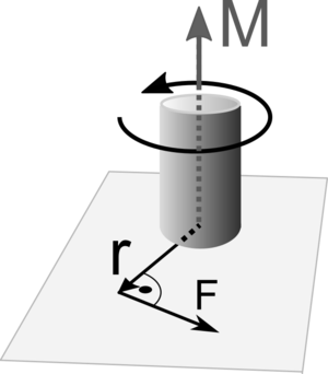
- To compensate for the relationship between the adjusting knob diameter and detent torque. The larger the diameter of the adjusting knob, the longer the lever (r), which acts perpendicular to the centre axis of the shaft, and the less force (F) is required to turn the adjusting knob and thus the axis of the encoder at the same detent torque.
Schmitt trigger

Many encoders have an integrated Schmitt trigger. The Schmitt trigger is an electronic circuit. The data sheet of each encoder contains a (block) diagram of the encoder electronics. From this diagram it can be seen whether the encoder has an integrated Schmitt trigger.
With this circuit a change of state of the output signal between two fixed level states low/high and vice versa is realized. For this purpose, signal amplitudes at the signal input of the Schmitt trigger must change within a certain range, the so-called "treshold level". The general rule is
- a Schmitt trigger always outputs square-wave signals
- if the frequency of the input signal changes, then the frequency of the output signal also changes
- the waveforms of the input signals at the Schmitt trigger can be different. For a level change to occur at the signal output of the Schmitt trigger, the signal amplitude of the input signal must change in the range of the switching thresholds
The use of the Schmitt trigger circuit has the following advantages:
- The increments are transmitted at the signal output as clearly defined square-wave signals displayed without a smoothing of signal edges
- The rise- and fall time between the level states (high/low) is significantly reduced
- Ageing characteristics of the light emitting diodes in continuous operation contribute to a decrease in luminous intensity during the operating period, or ageing of the optical system itself leads to a reduction in the signal level at the output of the phototransistors of the rotary encoder and thus also to changing switching characteristics. The Schmitt trigger is also used to effectively compensate for these ageing effects.
A disadvantage of encoders with integrated Schmitt triggers can be the slightly higher power consumption. This negative accompanying effect is often compensated for by the use of CMOS-based semiconductors in the encoder, which have a reduced overall power consumption.
Detent mechanism
There are usually three methods on the market for realizing a detent by means of a mechanism:
- Spring steel
- Metal ball + spiral spring
- Magnetic pole wheel
A good detent mechanism is characterized by largely unchanged detent properties over the entire service life of the encoder. As a manual operating element, for example, this means
If the service life of 1 million shaft revolutions is stated for an encoder and if the setpoint were changed 80 times a day by manual actuation, the threshold of 1 million actuations would not be exceeded until after more than 34 years. 80 manual changes of state per day, 365 days per year are already far too high for most applications. Surveys have shown that rotary encoders are actuated significantly less than 100,000 times on average during their lifetime. In fact, only a few tens of thousands of actuations during the lifetime of an application are realistic.
Spring steel
In spring steel detent mechanisms, a spring plate snaps into recesses in the housing, the running surface of which is often greased. These detent mechanisms often show a strongly decreasing detent behaviour depending on the shaft actuation and are mostly found in encoders with a limited lifespan.
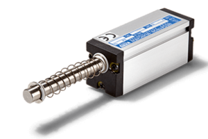
Metal ball & spiral spring
The latching mechanism is realized by two metal balls, which are arranged opposite the shaft inside. The balls are pressed by two spiral springs onto a gear rim which is mounted on the shaft. A lubricant is applied to the teeth of the gear rim. This principle has been significantly developed and continuously improved by us. It offers optimum properties in terms of compact design, product life and high efficiency.
Magnetic pole wheel
A latching mechanism with a magnetic pole wheel is a technically high-quality solution that offers maximum product life with consistent latching behaviour.
A circular permanent magnet (pole wheel) is mounted on an encoder shaft, which is alternately magnetized at equidistant intervals (north/south). Small circular magnetic metal plates are arranged around the permanent magnet at equal distances from each other in the encoder housing. When the shaft is rotated, the pole wheel is also moved and reciprocal magnetic effects occur between the pole wheel and the metal plates. A repelling (north/north or south/south) and an attracting (north/south) force acts between the alternating magnetic fields of the pole wheel and the metal plates in the encoder housing. If there is no rotation of the shaft, the shaft will remain in one position, which is equivalent to a snap-in. The pole wheel principle requires considerably more space than other methods and is more complex and expensive to manufacture.
Inhibition of rotation (increased operating torque)
Encoders are very often used as manual adjusters. Therefore, they are optimized for manual operation of the shaft.
A higher operating torque is required for safe input of setpoints. This is the only way to set precise setpoints and to counteract unintentional rotation of the shaft.
The torque describes the rotational effect of a force which must act on the shaft in order to rotate it. The unit for the torque is Newton metre [Nm]. In order to increase the torque, rotary encoders with plain bearings are used, and the anti-rotation is achieved by means of a damping grease and/or spring element to generate additional friction. The use of a ball bearing makes no sense due to the low (breakaway) torque.
The torque must be specified taking into account the operating temperature and the number of shaft movements. The lower the operating temperature, the higher the operating torque. A longer standstill of the shaft and the confirmation speed (rpm) also have an influence. Often the torque is specified in a data sheet at room temperature and an actuating speed with constant 10 rpm.
For technical reasons it is not possible to represent the specification by means of a single value. This is only possible for one value range. Reasons for this are mainly tolerances of the shaft bearing and shaft as well as the quantity and positioning of the damping grease on the shaft and shaft bearing. Typical information about an operating torque in data sheets is
0.1 ≤ M ≤ 0.6 Ncm / 0.3 ≤ M ≤ 1.3 Ncm (@RT, 10 rpm)
The abbreviation RT stands for the reference of the torque measurement to the room temperature and is located between 19 °C and 21 °C according to the standard for residential and office buildings.
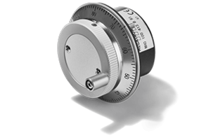
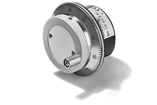
Knob topic
In addition to the characteristics such as operating torque or detent torque, the rotary knob plays a decisive role in the haptic properties of a rotary encoder. Mass and outer diameter are the most important factors here.
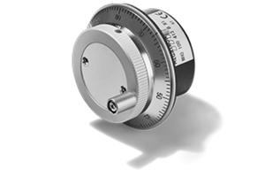
Handwheels usually have a setting head with a high mass. If a fast rotary movement is performed and the setting head is released, the relatively high mass of the setting knob prevents the encoder shaft from stopping abruptly. This means: The increased mass of the rotary knob leads to a briefly continuing rotary motion of the shaft (overshoot characteristic due to mass inertia). This can be advantageous for setpoints that need to be changed quickly, because this effect supports the rotation.
With rotary encoders from MEGATRON in the handwheel version, a crank handle is also integrated in the rotary knob. In the case of handwheels, the rotary knob is part of the scope of delivery and is already attached to the rotary encoder. For all other rotary encoders, a rotary knob must be selected as a further accessory.

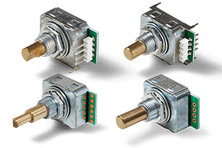


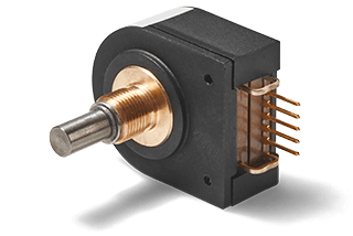
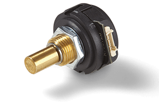

Panel encoders with optoelectronic sensor technology are optical incremental encoders and provide their output values in the form of pulses. They are often used as man-machine interface for precise specification of setpoints. For practical use, the operating elements often offer additional detents and push button function. Since they are operated manually, the product configuration has a great influence on the operating feel.
These include, among other things, a turning inhibition, push button switch and detents tailored to the requirements of the application. It is the turning inhibition, for example, which prevents unintentional adjustment and, in combination with detents, determines the haptic properties. With our portfolio we cover a wide range of needs. Furthermore, we are your partner for the optimization of the panel encoder in your application.
After all, it is the application requirements that dictate the type of operation. We will be pleased to advise you and together with you define the optimum product for your "design in". Our aim is to supply the best functional and economical product for your application. In doing so, we accompany you as a long-standing partner with high delivery reliability and assured quality products over the entire lifespan of your application.