 EN
EN DE
DE ES
ES FR
FR PT
PT IT
IT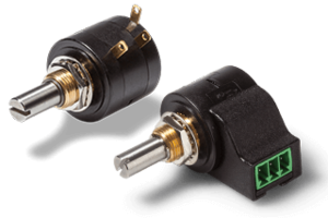


Wirewound Potentiometers
Multi-turn and single-turn versions
Guide Wirewound Potentiometers
Index
Resistance element of wirewound potentiometers
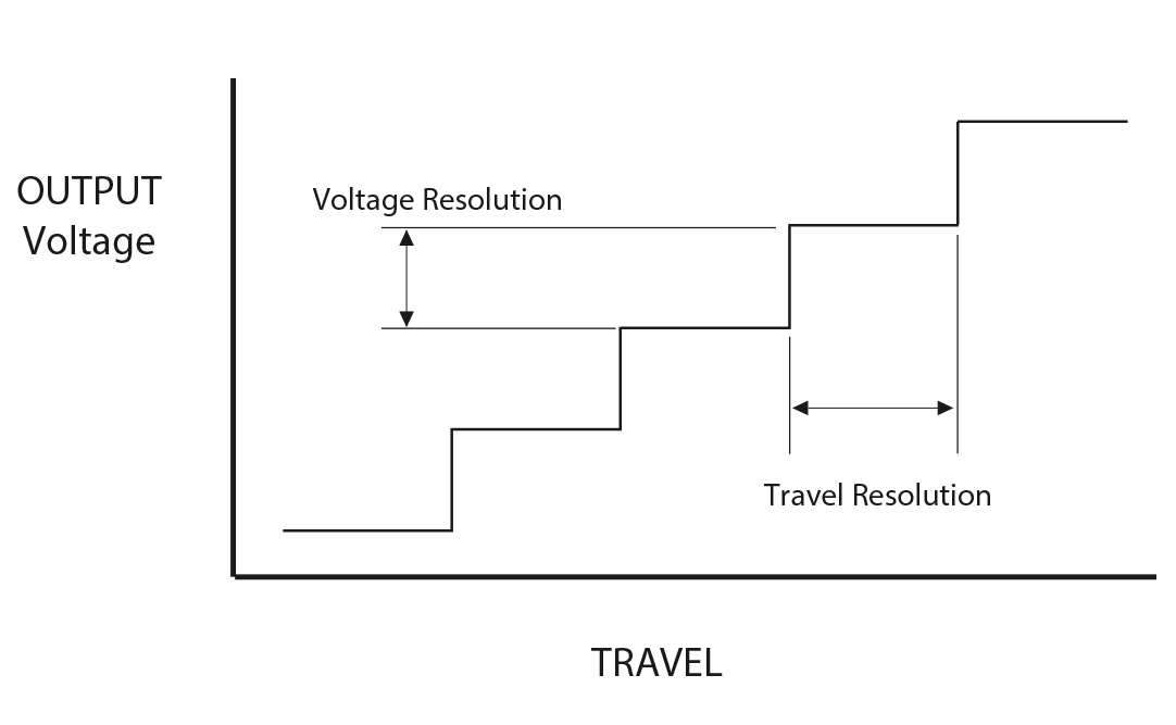
The production of the resistor element for wirewound potentiometers requires a high degree of mechanical precision in the manufacturing process, and few manufacturers today are able to meet this challenge: A hair-thin resistance wire is wound around a carrier core under a defined tension. Depending on the desired total resistance value, different metal alloys are used and depending on the total resistance value the number of wire windings around the carrier core is determined. When the voltage potential is tapped, the wiper touches only a small part of the winding surface. However, this surface is not completely flat due to the windings. For this reason, wirewound potentiometers produce winding jumps in the output signal, which appear as small steps.

Wirewound Element
Resolution of wirewound potentiometers
High resistance wirewound potentiometers have a higher resolution
The easiest way to improve the resolution of wirewound potentiometers is to increase the number of windings. This will make the windings denser and reduce the jumps in the output signal described above. As the wire length increases, the total resistance value increases. Depending on the application, this can be an advantage, e.g. when low power dissipation is required. Due to this correlation, a compromise between resolution and total resistance often has to be made when selecting the parameters.
Formula for calculating the resolution:
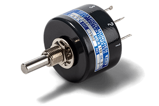
Example series RP19/20
- maximum electrical travel is 355°
- @ 5kOhm 1000 windings
Formula: 355° / 1000 turns = approx. 0.355 degrees
Formula for calculating angular degrees:
\(θ = \frac {Vout} {Vin} * \text{effective electrical angle of rotation}\)
Example: \(θ = \frac {4} {5} * 355° \approx284°\)
With a total angle range of 0° to 355° and a voltage range of 0 to 5 V, if approximately 4 V is measured at the slider, this would correspond to an angle of approximately 284°. However, this is a theoretical value as potentiometers have backlash at the end positions and resistance tolerances.
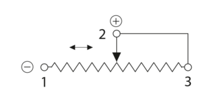
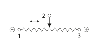
Circuit methods of wirewound potentiometers
The permissible load on the signal output is limited by the maximum permissible wiper current. In principle, wirewound potentiometers are also suitable for applications with a so-called rheostat circuit as a variable resistor, where a certain base load occurs. However, we recommend the use of a voltage divider circuit to take full advantage of the quality and performance of our wirewound potentiometers.
However, wirewound potentiometers can be useful in some applications (e.g. when using older PLCs) where it is not possible to implement a voltage divider circuit. Within the specified performance limits, they can withstand straining wiper currents without damage.
Load capacity of the resistance element
| Example | Voltage U | Resistance R | Power P | Application possible? |
| 1 | 20 V | 1 kΩ | 0.4 Watt | yes |
| 2 | 30 V | 1 kΩ | 0.9 Watt | no |
| 3 | 30 V | 5 kΩ | 0.18 Watt | yes |
| 4 | 100 V | 10 kΩ | 1 Watt | no |
| 5 | 100 V | 20 kΩ | 0.5 Watt | yes |
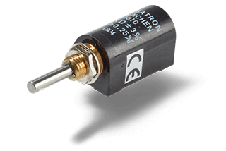
Example RP22/23 series
- available resistance values (10...500Ω) 1, 2, 5, 10, 20 kΩ
- max. load capacity 0.5 Watt
The following applies to power loss:
P = U² / R (power P = voltage U² / resistance R)
From this example, it is immediately clear that the 1 kΩ potentiometer cannot be used at an operating voltage of 30 V, because otherwise the load on the resistive element would be too high. Please also consider the additional restrictions for the ambient temperature.
Resistance elements in comparison
| Resistive element | Conductive Plastic | Wirewound | Hybrid |
| Lifespan | ++ | 0 | + |
| Signal quality / resolution | +++ | + | +++ |
| Linearity | +++ | ++ | ++ |
| Electrical travel | max. 360° | 10800° | max. 3600° |
| Operational speed | ++ | - | ++ |
| Max. wiper current | - | + | - |
| Shock / Vibration | - | -- | -- |
Legend: +++ best | ++ very good | + good | 0 OK | - low | -- unfavourable | --- not appropriate
Decision support
Wirewound potentiometers are available in single and multi-turn versions. Wirewound potentiometers offer very good linearities and very high electrically effective angles of rotation; up to 355° for single-turn and up to 10800° for multi-turn. Wirewound potentiometers are the right choice for applications with high resistance tolerance requirements.
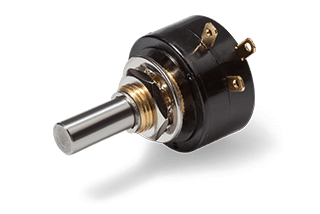
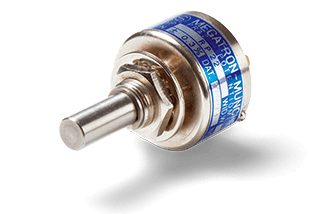
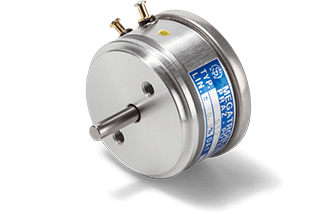
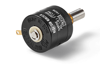
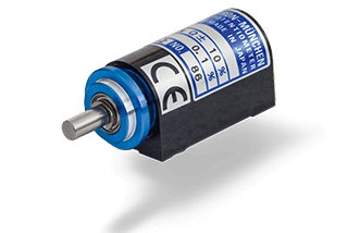
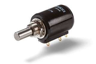
RP19/20 singleturn
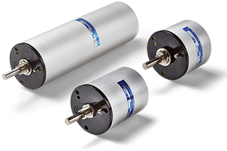
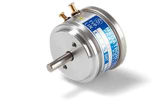
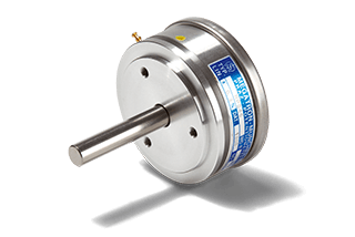
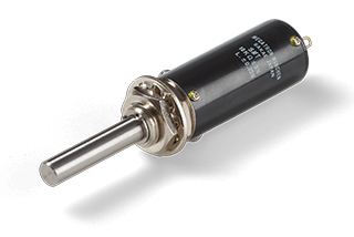
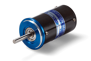
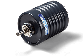
Series 46 multiturn
Wirewound compared to conductive plastic potentiometers
Due to the uneven nature of the resistance wire winding, the output signal is slightly stepped. In addition, over time, more electrical noise is generated due to greater wear than is the case with conductive plastic or hybrid potentiometers. However, the best linearity is achieved with conductive plastic potentiometers. In addition, the lifetime of conductive plastic potentiometers is the longest of all technologies.
Wirewound potentiometer technology is slightly more robust to low frequency shock and vibration than conductive plastic potentiometer technology. However, we recommend the use of non-contacting sensors where vibration is a factor.
At very slow speeds, a "creeping" contact is created between the wiper and the resistor element. Under these conditions, a safe electrical connection can only be guaranteed if a certain minimum current is applied to the contact. Experience has shown that approximately 100 µA at the slider is sufficient. However, we recommend the use of conductive plastic or hybrid potentiometers for measurement tasks involving very slow movements.
Wirewound potentiometers are not suitable for operating speeds above 40rpm. For higher requirements, our conductive plastic and hybrid potentiometers are designed for speeds up to 400 rpm.
Limit switches are used on some models, particularly in safety critical applications. These detect when a multi-turn potentiometer has reached its mechanical end position. The microswitches used have separate connections and their own specifications for maximum current consumption.
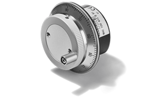
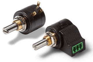
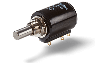
Wirewound potentiometers are often used as panel encoders

Multiturn potentiometers with wirewound resistors are often used for setpoint adjustment in handheld applications, where long life and extremely tight tolerances, such as those of hybrid potentiometers, are usually of secondary importance. In addition, the slightly better shock tolerance of wirewound potentiometers in the low frequency range can be an advantage in these applications. Hybrid potentiometers are used where long life, excellent linearity and a high electrically effective angle are required.
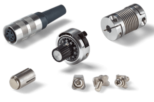
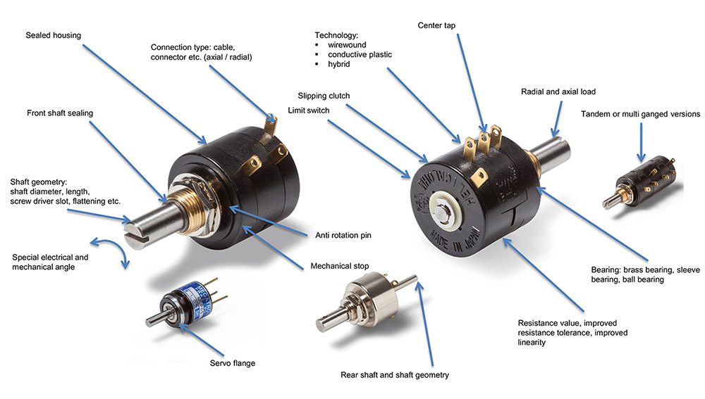
Product customizations
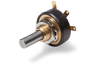
Our wirewound potentiometers are available in bushing or servo flange versions, each with their own unique features. A variety are available with or without mechanical stop, with optional rear shaft, centre tap(s) and in tandem/multi-turn versions. Specials include shaft modifications, special torques, sealed housings, special electrical and mechanical rotation angles, special resistance and linearity tolerances, assembly of gears and other mechanical parts, assembly of cables and connectors, and much more. As a specialist in industrial sensor technology, we are the ideal partner for your application because we have the highest quality standards and delivery reliability to meet your technical requirements.


Wirewound potentiometers cover angles up to 10800°. They achieve top ratings for linearity and resistance tolerances. Special functions such as centre taps or limit switches can also be integrated. The components have slightly higher tolerances for the permissible wiper current, which can be an important selection criterion in special applications.
The portfolio of wirewound potentiometers is divided into single-turn variants (up to 355°) and multiturn products (up to 10800°). The offer goes from miniaturized versions, with the smallest 10-turn potentiometer in the world, to versions with reinforced shaft bearings of up to 4 N. Despite the wide selection, these products often require technical product adaptations to best meet the requirements of the application.
MEGATRON is your partner for the optimal adaptation of the product to your application. Our aim is to provide each customer with the best functional and economic result. With high delivery reliability and assured quality products, we focus on long-term partnerships and accompany you throughout the entire life cycle of your application.